Moog SlayerBy Atom Smasher
Filter Mod for korg EX-800 and Poly-800
atom@suspicious.org
Samples, Reviews, Tech
Notes
It all started when my comrade, Tom, asked me to do the original
filter mod to his EX-800.
I gave him back his synth, and he said "Atom, it does this," while holding
his fingers about an inch apart. He continued, "make it do this," now holding
his hands about a foot apart. Back to the bench.....
This time, when I took it back to him, he plugged it in, and said "Holy shit!
It's like this!!!", grinning, and holding his hands as far apart as he could get
them.
At the time I wasn't that big a fan of the Poly-800 series... but after doing
this mod, I picked up an EX-800 for myself (pictured here).
| This thing can do
dangerous sounds, like the
speaker-blowing (and ear-blowing!) sounds of old
modular synths. It's really sick.... In addition
to the usual disclaimers (if you break it, it's
your problem, not mine!), I'd like to also point
out that I will not be responsible for blown
speakers, amps & ear-drums.
| | |
| --
-- | | | | |
If anyone wants to send me samples of their modded synth, maybe I'll post it
here.
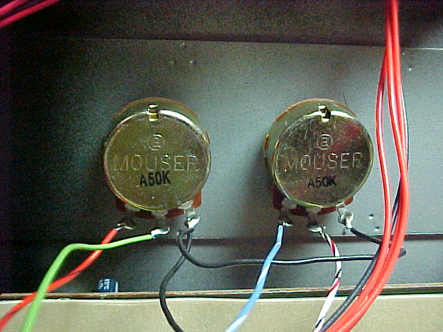
- First, install the new pots in the front panel.
Knobs, front
Knobs,
back
Knobs, back, close
Use 50K-Ohm audio taper pots.
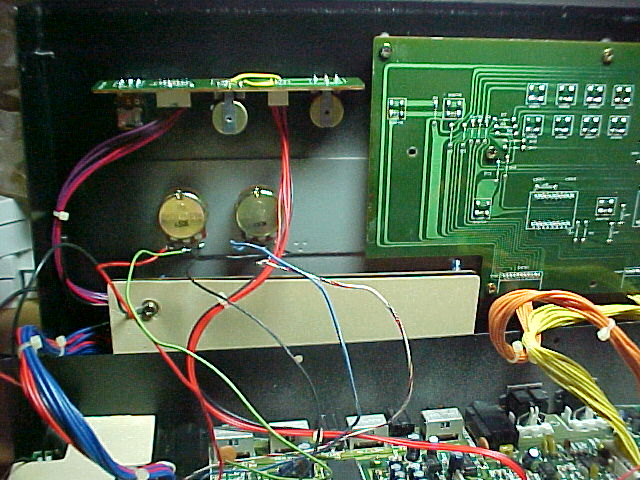
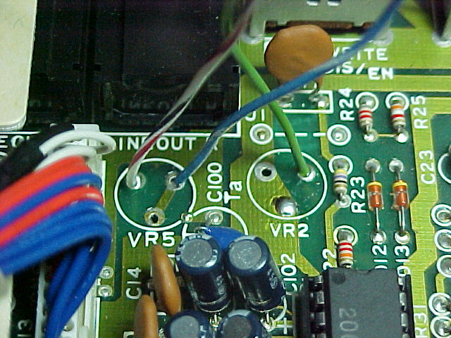
- Remove pots "VR2" and "VR5" from the main board. They are located behind
the audio-out jacks.
Main board.
Pictured with wires leading to the new pots.
Note how the dots in the
diagram relate to the holes on the board.
- Wire it all up, like this:
                                                            + VDC  *
                                                                   |
                                                                   |
                                                                   |
                                                                   \
                                                                   /
                                                     470-510 Ohm   \
                                                                   /
                                                                   \
                                                                   /
                                                                   |
                                                                   |
              *RESONANCE*                           *CUTOFF*       |
               50K Audio                            50K Audio      |
                                                                   |
         +-----/\/\/\/\/\-----+               +-----/\/\/\/\/\-----+
         |                    |               |
         |        /|\         |               |        /|\
         |         |          |               |         |
         |         |          |               |         |
         |         |          |               |         |
        ---        |          |              ---        |
ground  ///        |          |      ground  ///        |
                   |          |                         |
                   |          |                         |
        	   |         /                          |
		   |        /                           |
		   |       /                            |
	           |      /                             |
	           |     /                              |
		   |    /                               |
		   o   o                            o   o

		     o                                o

		    VR5                              VR2
| |
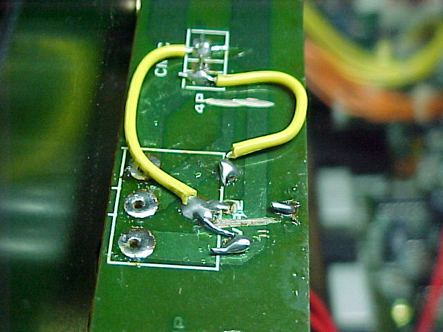
The
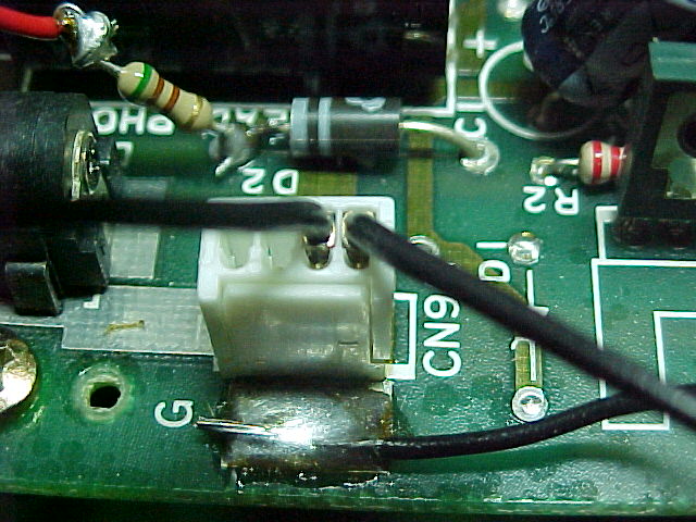
ground (black wire) and +V (red wire & resistor) are wired up here
There is a
diode just next to where the power jack is. Wire up the 470-510 Ohm resistor
to the cathode. Make sure there is heat-shrink or tape over the resistor, or
else it might short out against the power-jack, or something. This picture
shows it without the heat-shrink, for clarity. Wire up the ground connection
to the big pad, just next to the power jack and connector "CN9".
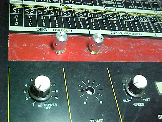
- While I had the unit opened up, I decided to fix the TUNE knob that
always got knocked out of tune.
My solution is a knob that has to be
turned with a small screwdriver, to avoid unintended adjustments. You can see
it in this picture.
- Remove the small board with the tuning knob. Remove the tuning knob from
the board.
- With a Dremel tool, shorten the shaft to about
3/16 in (about 5mm) and cut a slit in
it, so it can be turned with a screwdriver.
- Using a small drill, cut four holes in the small board, so the tuning
pot can be moved back, about 3/8 in
(about 9-10 mm).
See picture.
- Cut the circuit board traces, and re-wire the tuning knob.
- Like (almost) always, assembly is the reverse of disassembly.
- Have fun!
Knobs
The front panel inlay was removed, before I
drilled the holes. If I ever rack-mount this thing, I might use the original
front panel.
Also, you can see that the tuning knob is now recessed.
Knobs 2
View shows the knobs, but they can be
mounted more towards either side, as long as they don't interfere with the
display/button board.
Knobs 3
Close up of knobs shows wiring.
Main Board
Note how the holes here line up with
the holes in the diagram.
POWER!!
Don't forget the heat-shrink!! Or
sparks will fly!!
Tuning knob
Even if you don't do the filter mod,
this is a cool mod by itself.
The holes towards the left are the original
mounting holes. The pot is moved away from the front panel (towards the right,
in this picture) into the new holes, and wired-up like a broken jaw to the
connector terminals.